Isostack Tool Help – Right Panel
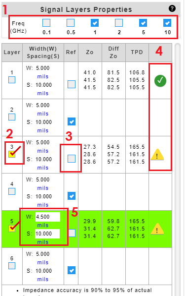
  1. Check to select frequencies to calculate impedance.
  2. Check to highlight the copper layer of interest.
  3. Uncheck reference check box to designate a signal layer. By default, all layers are treated as a reference plane.
  4. 4. A ‘green’ Okcheck mark indicates that the input criteria meet the constraints for the equations used in IsoStack. A ‘yellow’ Warning warning sign indicates that the input criteria do not meet the constraints for the equations used in IsoStack. Click on the icon to reveal the parameters and criteria.
  5. Click to enter or edit trace properties.
NOTE:
Formulas from IPC-2141A Design Guide for High-Speed Controlled Impedance Circuit Board.

16 July 2021

Related Posts

UAV FW Blog
PCBs Lighten the Loads for Commercial UAVs
Drones or unmanned aerial vehicles (UAVs) are typically associated with military users, although a growing number of applications are being found for UAVs in commercial, industrial, and even medical markets. Commercial users await approval from key government agencies, such as the U. S. Federal Aviation Administration, for properly authorized use…
Adolf Sommer Post2
Base Materials for Printed Circuit Boards in Aerospace Applications
Printed circuit boards have become an integral part of modern electronics. They have evolved from a pure component carrier to an active and important electronic component in their own right. The use of high-frequency materials in particular opens up new possibilities in radar technology or phased array antennas.  …
Isostack Tool Help – Left Panel
Click on core or prepreg tab to display the materials for your design. You can right click and drag and drop a core or prepreg item into the stack up editor. Any unused core or prepreg item can be removed from the list by clicking on the X. The Dk…