Isostack Tool Help – Right Panel
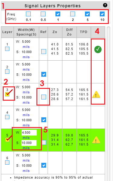
  1. Check to select frequencies to calculate impedance.
  2. Check to highlight the copper layer of interest.
  3. Uncheck reference check box to designate a signal layer. By default, all layers are treated as a reference plane.
  4. 4. A ‘green’ Okcheck mark indicates that the input criteria meet the constraints for the equations used in IsoStack. A ‘yellow’ Warning warning sign indicates that the input criteria do not meet the constraints for the equations used in IsoStack. Click on the icon to reveal the parameters and criteria.
  5. Click to enter or edit trace properties.
NOTE:
Formulas from IPC-2141A Design Guide for High-Speed Controlled Impedance Circuit Board.

16 July 2021

Related Posts

A Tour of the New Isola Factory: Investing in North America
A Tour of the New Isola Factory: Investing in America
I recently toured Isola’s new 118,000-squarefoot low-volume, high-mix manufacturing facility in Chandler, Arizona. The facility’s construction began in 2020 and, like many building projects, was delayed because of the COVID19 pandemic. Building a new factory during the pandemic was certainly a challenge but the team persevered and the new greenfield…
Isostack Tool Help – Central Panel
When multiple resins systems are used, a hybrid notification will appear. Checking the shield or mask check box will add surface finish and soldermask to the outer layers. Units in mils, mm and µm can be selected. The Zoom function will compress the stack up to reduce scroll distance. Clicking…
Isostack Tool Help – Left Panel
Click on core or prepreg tab to display the materials for your design. You can right click and drag and drop a core or prepreg item into the stack up editor. Any unused core or prepreg item can be removed from the list by clicking on the X. The Dk…