The Importance of Circuit Board Material for Millimeter-wave Circuits
Growing demands for higher data rates and real-time video require wide bandwidths that are only available at 24 GHz and above. This calls for more than simple network infrastructure additions or modifications as the shorter wavelengths at these frequencies propagate over shorter distances than at microwave frequencies.
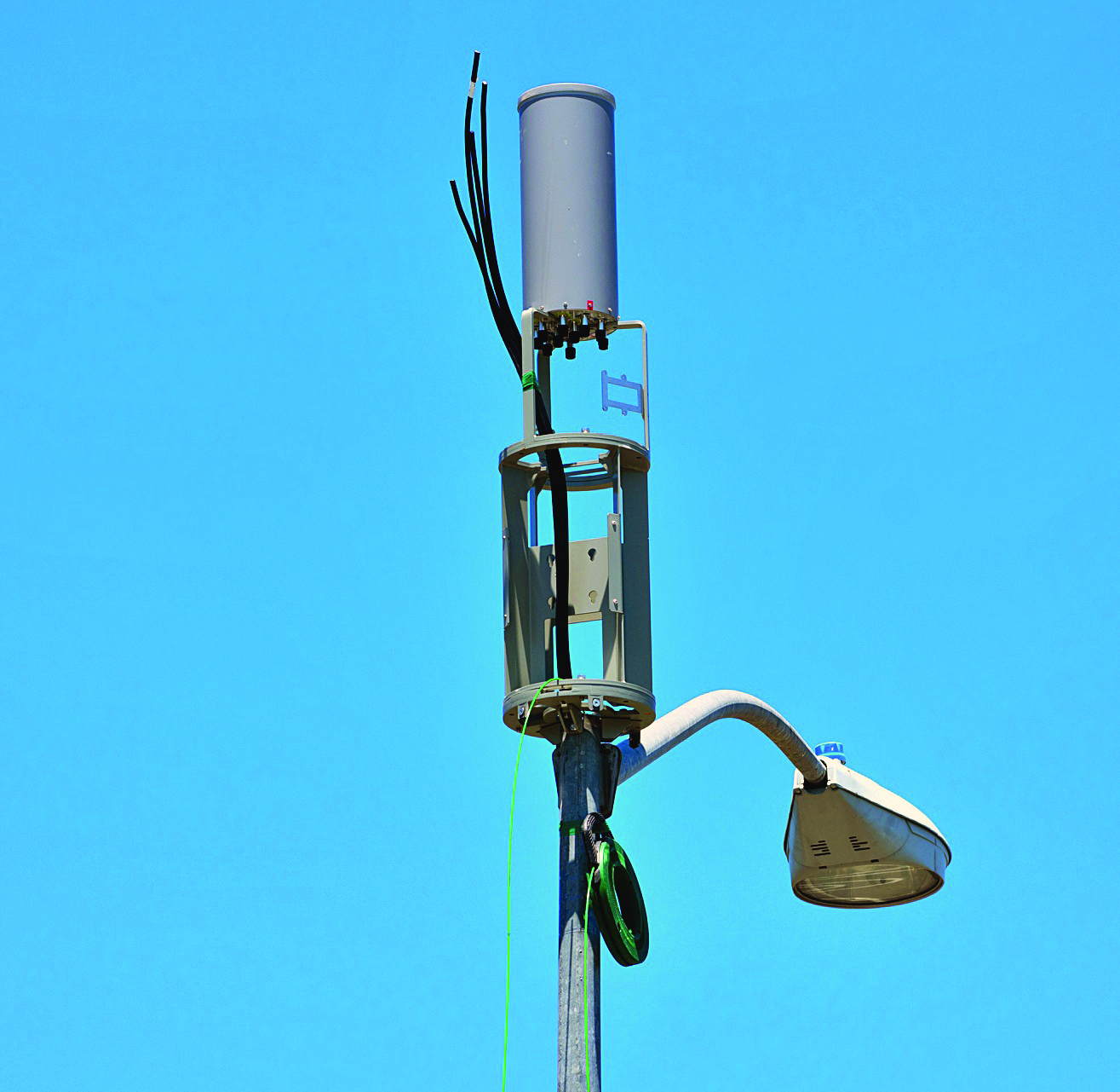
For expanding 5G network coverage and performance, 5G cells will be much smaller than their lower-frequency counterparts (Figure 1), while 5G macro cells employ distributed antenna systems to bring signals at 6 GHz and below to many users over large areas. The same approach does not work effectively at millimeter-wave frequencies where the small signal wavelengths have limited propagation distances and signals can be blocked by nearly anything.
Such small cells will require densely-packed circuitry with high functionality and printed-circuit-board (PCB) materials that can support the performance needed at millimeter-wave frequencies. Fortunately, ultra-low-loss materials have been developed to support the circuits needed for these small cells as some 5G telecommunications equipment designers expect operating frequencies to ultimately reach 140 GHz. Raw circuit materials such as I-Tera® MT40, Astra® MT77, and Tachyon® 100G from Isola Group meet the needs of 5G small cells that can economically and reliably provide the coverage and capacity for present and future 5G wireless cell networks.
Circuit materials for 5G small cells must support high circuit densities and often a blend of analog, RF and microwave, high-speed-digital, and power circuitry within indoor and outdoor 5G base stations and repeaters often about the size of a shoe box. Whether for urban or rural areas, the local zoning codes will usually determine the size and appearance of a small cell and where it can be located. Although in several shapes and sizes with different power levels, the goal of all 5G small cells is the same: to fill in any gaps in coverage and capacity left by larger, more traditional cell towers and base stations.
Small cells are usually defined in ascending order as femtocells, picocells, microcells, and metro cells, with larger small cells transmitting at higher power levels and reaching greater numbers of users. For example, the two smallest 5G cells, femtocells and picocells, are designed for indoor use such as within buildings, as well as outdoor use, and can support as many as 32 and 128 users, respectively, at transmit power levels up to about 5 W. The larger small cells, microcells and metro cells, are meant for outdoor installation and for 256 or more users at transmit power levels as high as 20 W.
In addition to differences in size and power, the small cells may employ different types of antennas and backhaul interfaces to the 5G cellular network that may include wired, wireless, and fiber-optic interconnections. In most cases, the small cells are designed and assembled to be as inconspicuous as possible, adding millimeter-wave coverage and capacity to larger and more conspicuous 5G cell towers and repeaters.
Shrinking Circuits
For economical and efficient 5G small cell circuits capable of high performance through millimeter-wave frequencies, preferred circuit materials have a low dielectric constant (Dk), low dissipation factor (Df), and high glass transition temperature (Tg). Dk is a measure of the capacitance between two conductors on a dielectric material compared to those conductors at the same distance from each other in a vacuum. Materials with higher Dk values can store more electromagnetic energy than materials with lower Dk values.
However, the flow of energy through the conductors is slower for circuit materials with higher Dk values. Lower Dk values also allow for wider transmission lines for the same dielectric thickness and have reduced conductor losses. For these reasons, circuit materials with low Dk are usually preferred as the basis for PC boards with millimeter-wave circuitry.
Signal power is often difficult to maintain at millimeter-wave frequencies, requiring circuit materials with the lowest possible loss. Different transmission-line formats such as microstrip or coplanar waveguide (CPW) are typically used for circuits at millimeter-wave frequencies, and the loss of each transmission-line technology is affected by various circuit material characteristics.
Transmission-line loss is a combination of the PCB’s conductor loss and its dielectric loss. Circuit materials with low Df exhibit low dielectric loss. Conductor loss, especially at millimeter-wave frequencies, is a function of the surface roughness of the conductor material. Low conductor loss is usually achieved with the smoothest, low-resistance copper conductor. The effects of conductor skin depth on transmission-line conductor loss have the greatest impact at the highest frequencies. For example, at 1 GHz, variations in copper roughness of less than 2.1 μm usually have a minimal effect on loss performance. But at 10 GHz, copper treatment variations of only 0.7 μm are enough to disrupt the conductance of those small-wavelength signals.
A circuit material’s Tg is a measure of the temperature at which the material’s thermomechanical properties change, above which the material loses mechanical stability. Circuit materials with high Tg are attractive for millimeter-wave and other circuits in small 5G cells because they have better heat resistance and very often lower moisture absorption than materials with lower Tg values.
For 5G small cells, circuit materials should also provide stable, consistent performance over wide operating temperatures and under conditions of high humidity, especially when meant for use in outdoor locations, and they should be capable of supporting high circuit densities to achieve the number of circuit functions required for a small package. In many cases, the use of environmentally friendly circuit materials such as halogen-free types may be preferred to standard circuit materials, especially for applications deemed to be environmentally sensitive.
Circuits at millimeter-wave frequencies are sensitive to variations in material thickness and rough surfaces of copper conductors on laminates. Thickness variations and rough conductor surfaces can result in variations in amplitude and phase due to the small signal wavelengths at millimeter-wave frequencies.
For consistent, low-loss conductance of millimeter-wave materials, the circuit materials should have smooth copper conductor surfaces and minimal dielectric thickness variations, with minimal physical changes caused by environmental factors such as heat and humidity. Such materials are usually denoted by high glass transition temperature (Tg) and low coefficient of thermal expansion (CTE) while also exhibiting low water (H2O) absorption so the material’s Dk will not be affected by operation during rainstorms in outdoor small cells.
Mining the Materials
To support a growing market in 5G small cells, circuit materials capable of providing the performance needed at millimeter-wave frequencies should also be economical and “process friendly,” compatible with machining and manufacturing steps and techniques used in transforming widely used circuit materials such as FR-4 into PC boards. Such compatibility makes it possible to combine lower-loss, higher-frequency circuit materials with standard materials such as FR-4 as part of hybrid circuit constructions using FR-4 for power-supply circuits and other functions not requiring the low loss of the RF, microwave, and millimeter-wave circuit materials.
As an example, I-Tera MT40 (RF/MW) very-low-loss laminate and prepreg materials (Figure 2) exhibit the low conductor and dielectric losses needed for maintaining good signal strength at millimeter-wave frequencies, evidenced by a typical Df of 0.0031 at 10 GHz. The Dk is 3.45 at 10 GHz through the z-axis or thickness of the material. The circuit materials have a high Tg of +200°C and provide the low moisture absorption and excellent thermal stability needed for densely packed circuits in small 5G cells, with a coefficient of thermal expansion (CTE) and total expansion through the z-axis of 2.8% from +50 to +260°C.
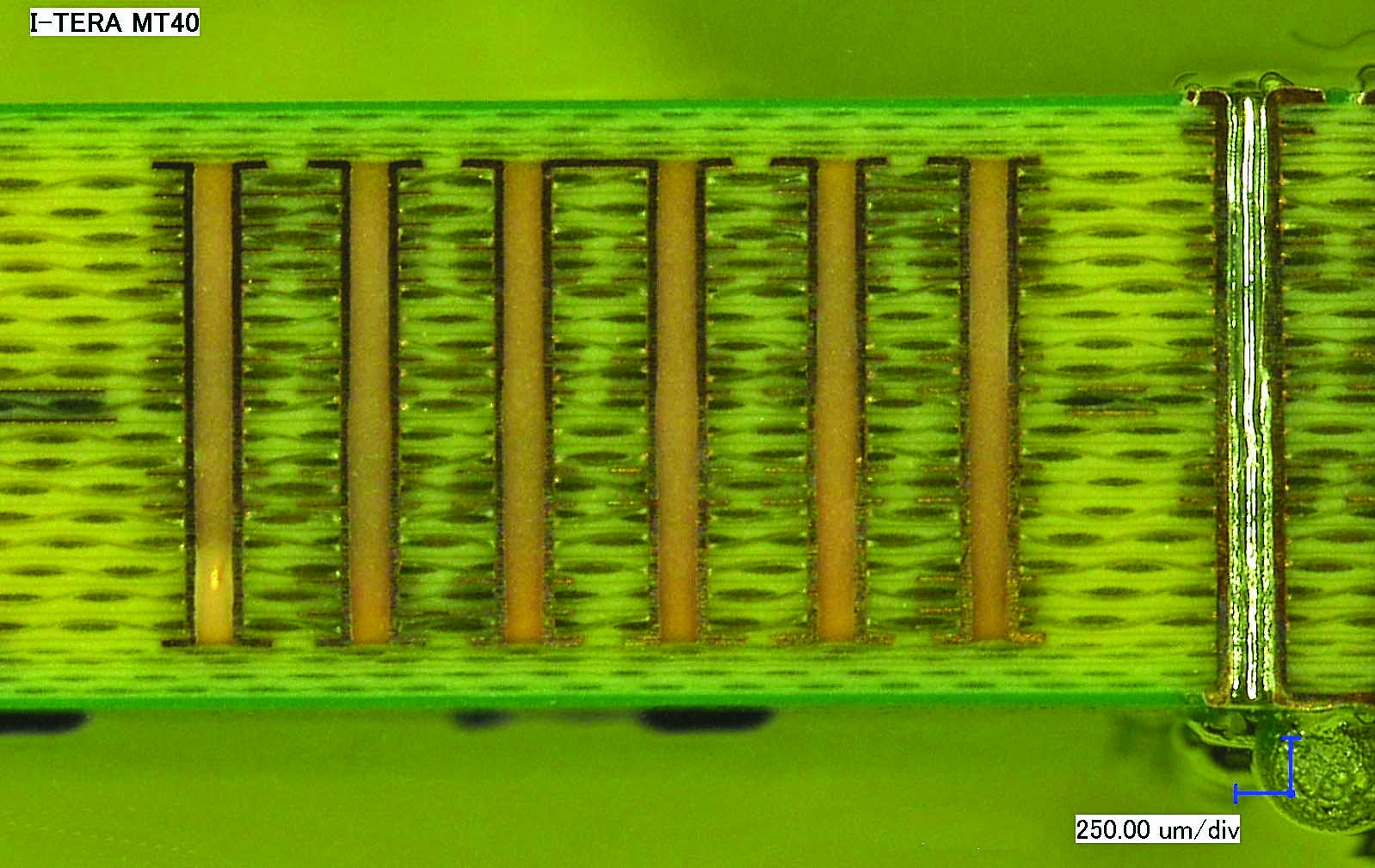
Figure 2: A sequential I-Tera® MT40 stack-up
The materials have the thermal conductivity needed for long operating lifetimes in tightly enclosed small cell housings at 0.61 W/m-K. And for small cells that will be mounted next to streetlights in highly populated areas, low 0.1% moisture absorption signifies reliable operation even during rainy weather conditions.
For millimeter-wave circuits requiring even lower loss, Astra MT77 ultra-low-loss laminates and prepregs (Figure 3) offer a cost-effective alternative to PTFE circuit materials, with a Df of a low 0.0017 measured at 2 and 10 GHz. The Dk, which is 3.0 at 2 and 10 GHz, also remains stable with temperature when analyzed from -40 to +140°C. These circuit materials have a Tg of +200°C and exhibit excellent thermal electrical and dimensional stability with low moisture absorption. They have a somewhat lower thermal conductivity than I-Tera MT40 (RF/microwave) circuit materials, at 0.45 W/m-K, but like those materials are FR-4 process compatible.
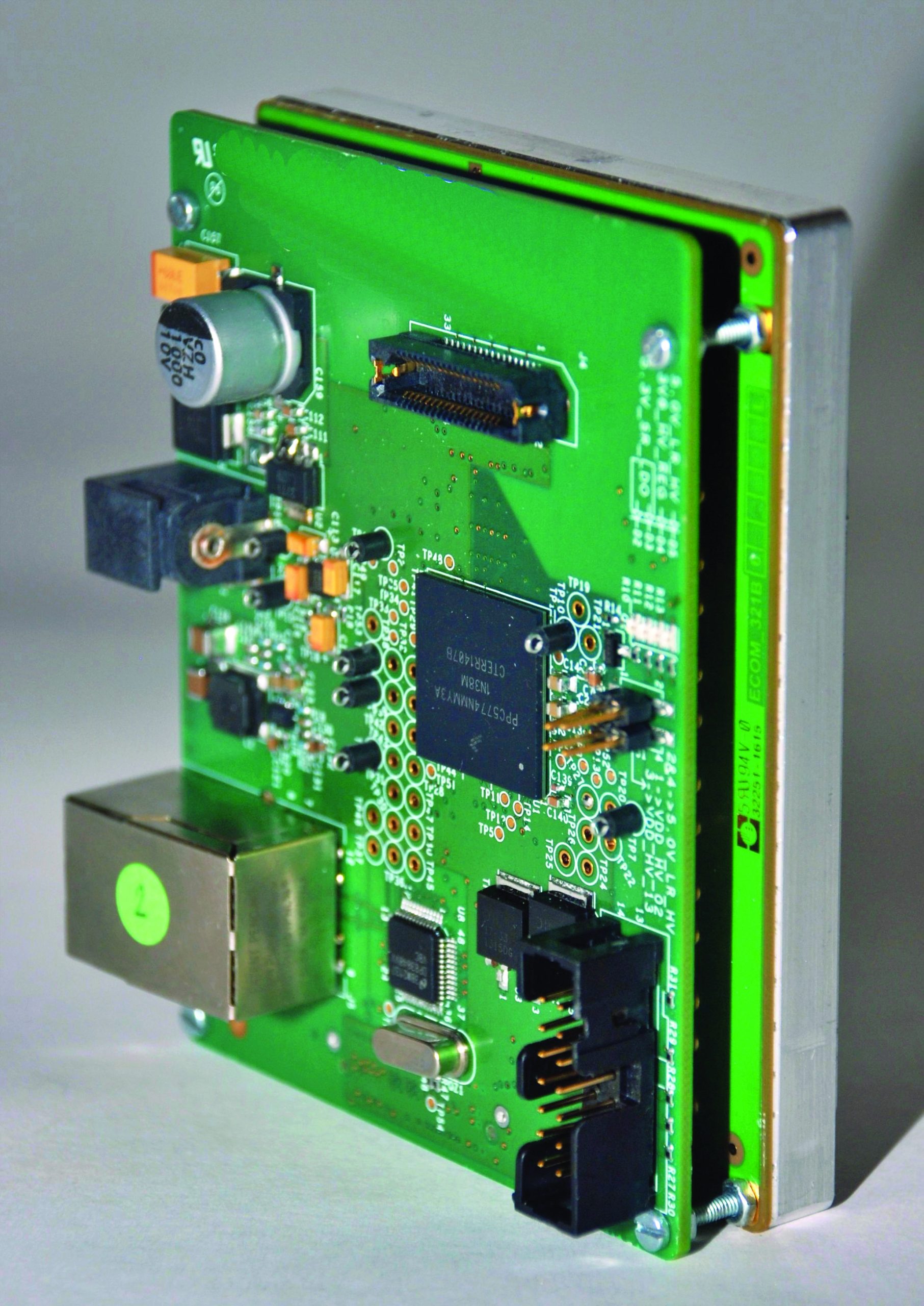
Figure 3: Astra® MT77 ultralow-loss laminates and prepreg circuit materials are compatible with standard loss circuit materials used in hybrid circuits in 5G small cells
For high-speed data circuits in 5G small cells, Tachyon 100G ultra-low-loss laminate and prepreg materials are also defined by a high Tg of +200°C. As with the other circuit materials, they have a low Dk that remains stable over wide operating temperature ranges. Tachyon 100G has slightly higher Dk and Df than Astra MT77 materials, although with suitable characteristics for HSD circuits operating at rates more than 100 Gb/s. The Dk is 3.04 at 2 GHz, 3.02 at 5 GHz, and 3.02 at 10 GHz. The Df is consistently 0.0021 at 2, 5, and 10 GHz. The materials undergo 2.5% total expansion through the z-axis at temperatures from +50 to +260°C and, like I-Tera MT40, Tachyon 100G circuit materials have low moisture absorption of 0.1%.
These three materials feature the high-performance characteristics required for low-loss circuits at microwave and millimeter-wave frequencies and high-speed data circuits operating at Gigabit speeds. However, they may provide performance that is not needed for some of the circuits in a 5G small cell, such as for control or power distribution circuitry.
Hybrid circuit designs have emerged in which circuit materials are selected according to function, such as FR-4 circuit materials for control and power circuits, and they are combined with the higher performance (and more costly) circuit materials needed for higher-frequency circuits. In addition to low-cost FR-4 materials, 370HR circuit materials (Figure 4) from Isola Group provide the processing and thermal compatibilities with higher-frequency, higher-speed I-Tera MT40, Astra MT77, and Tachyon 100G circuit materials to form economical but reliable multiple-signal, multilayer circuit assemblies that mix and match the circuit functions according to the circuit material characteristics.
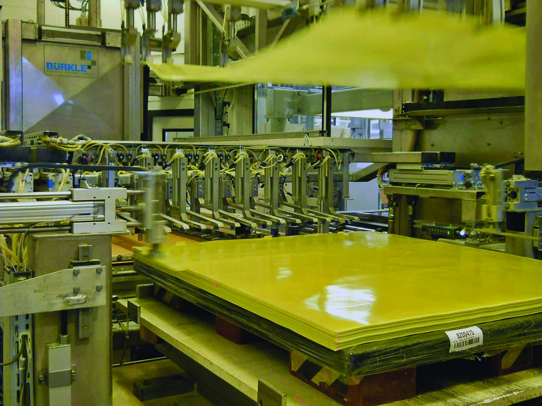
Figure 4: 370HR circuit materials in an automated manufacturing line at Isola
Compatible with FR-4 circuit processing, 370HR materials support similar circuit functions in 5G small cells as FR-4 materials, such as power distribution and control circuits. They have higher Dk and Df than the microwave/millimeter-wave circuit materials with good consistency for general purpose use. The Dk is 4.24 at 0.1 GHz, 4.04 at 2 GHz, and 3.92 at 10 GHz, while the Df is 0.0150 at 0.1 GHz, 0.0210 at 2 GHz, and 0.0250 at 10 GHz. The 370HR materials have a lower Tg at +180°C than the higher-frequency materials but undergo total z-axis CTE of 2.8% or less from +50 to +260°C. This provides thermal behavior consistent with the higher-frequency materials for minimal distortion caused by temperature when combined with the other materials in hybrid circuit assemblies.
Along with being physically inconspicuous, many 5G small cell manufacturers are setting new standards for zero carbon emissions and for circuit materials that will not emit toxic gases into the environment. TerraGreen® laminates are “environmentally friendly” while providing the properties needed for low-loss millimeter-wave circuit performance in 5G small cells.
These halogen-free circuit materials match the high Tg of the other materials, at +200°C with Dk that remains stable with temperatures from -55 to +125°C. The Dk is 3.45 at 2, 5, and 10 GHz with a Df of 0.0032 at those same test frequencies. As with the other circuit materials, TerraGreen is compatible with FR-4 circuit processing, is RoHS-compliant with lead-free processing, and is mechanically stable with temperature and consistent with the other materials, with total z-axis CTE of 2.9%.
Summary
The characteristics of circuit board materials are always important but millimeter-wave frequencies present additional challenges that aren’t as great a consideration at frequencies where, among other factors, signal traces are larger and easier to accommodate and achieving best performance is somewhat less difficult. Fortunately, Isola Group has developed families of materials designed specifically for use at frequencies that are increasingly used for both commercial and defense applications.
 by Alexander Ippich, Technical Director, Signal Integrity & Advanced Technology, Product Manager RF/Microwave OEM Marketing Europe
08 June 2022