Circuit Materials Meet Critical Needs for LEOS
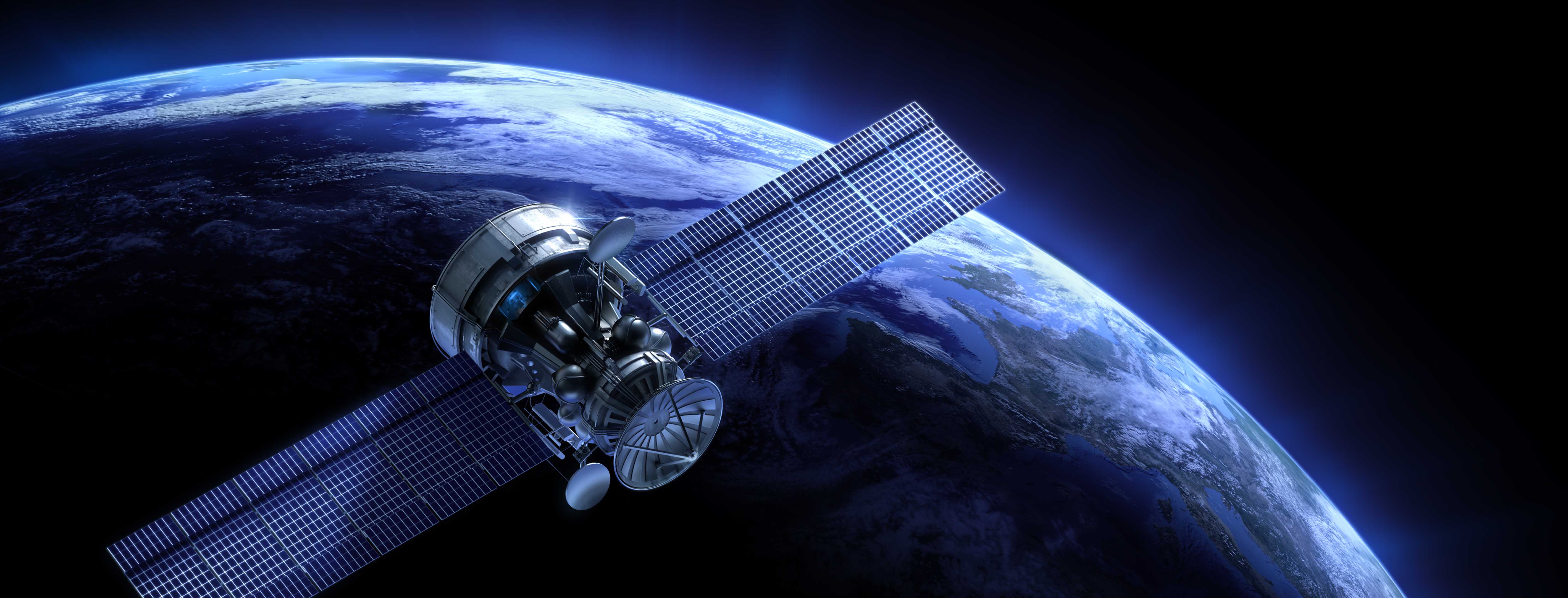
Thousands of satellites surround the Earth in their own orbital slots and even their own constellations, at distinct altitudes. They help communicate with distant places, track weather, and, with the Global Positioning System (GPS), find distant places here on Earth. Closest to Earth, low Earth orbit satellites (LEOS) are in the greatest numbers with totals growing rapidly. Circuit designers and manufacturers in need of circuit materials for RF/microwave and high-speed-digital (HSD) circuits for LEOS must seek substrates that can handle the rigors of a long, orbiting lifetime while meeting rigorous size, weight, and power (SWaP) requirements to keep a LEOS flying. LEOS (as well as their Earth stations) have a special set of needs for circuit materials and knowing those requirements can prevent a LEOS from getting lost in space!
Printed-circuit boards (PCBs) are typically tasked with carrying analog, digital, and even photonic signals within a LEOS under the extremely hostile operating conditions of space. Due to its orbiting motion, a satellite is facing the sun or shielded from it by the Earth, constantly going through thermal cycling as a result. Any circuit materials for LEOS should be thermally robust, over a wide temperature range and for a prolonged period. Circuit materials for space are typically fabricated to withstand a temperature range of -55 to +125°C without mechanical change or degradation in electrical performance.
Circuit materials integrated in an orbiting satellite, such as a LEOS, must be capable of handling greater thermal stress than the circuit materials supporting HSD or mmWave signals back on Earth because of the way temperature changes while in orbit. Temperatures drop rapidly while in the shadow of Earth and rise quickly when a satellite returns into direct sunlight. Circuit materials with good thermal conductivity characteristics can help dissipate the heat produced by direct sunlight.
Circuit materials in LEOS must be prepared for the vacuum of space since dielectric materials tend to lose mass in a vacuum. Outgassing is a phenomenon during which air or other gas trapped within a circuit material during PCB production is released in an ultrahigh vacuum (UHV). It can have unwanted side-effects, forming condensation on PCBs which increases the insertion loss of transmission lines, especially at the increasing number of millimeter-wave (mmWave) frequency bands that will be used for communications in LEOS.
Circuit materials well suited for LEOS should have low outgassing rates, for example, a loss of mass of less than 1% when tested according to ASTM standards. Outgassing can occur during PCB production when circuit materials are subjected to elevated temperatures during bonding and soldering. Standards such as IPC-1601 define methods for baking circuit materials to eliminate or at least minimize outgassing.
LEOS and mmWaves
As the numbers of LEOS increase in orbit, with growing use of mmWave frequencies, reliable, long-lasting circuit materials become even more essential components in the production of low-maintenance LEOS. Whether on Earth, at sea, or in space, circuit materials are characterized by a list of key parameters which indicate their expected behavior under certain conditions. Especially critical for dependable mmWave circuit performance is the consistency of a circuit material’s dielectric constant, Dk. It should not change with temperature, frequency, or time since even the slightest changes can mean variations in the characteristic impedance of the transmission lines that carry a circuits high-frequency and HSD signals. A circuit material with low temperature coefficient of Dk (TCDk) provides the consistent Dk with temperature needed when installed within a LEOS, such as for antennas.
Circuit materials capable of supporting high-speed, high-frequency transmission lines typically exhibit a Dk in the range of 3.0 to 3.5 which yields fine circuit dimensions for a given characteristic impedance. Because signal power is limited in HSD and mmWave circuits, loss from the circuit material’s conductors and dielectric content, as signified by the material’s copper surface roughness and dielectric dissipation factor (Df), should be as low as possible for mmWave circuits, where loss of signal power can be even more critical than for HSD circuits.
LEOS orbit the Earth at altitudes below the radiation belts that can haunt satellites at higher altitudes, such as medium Earth orbit satellites (MEOS) and geosynchronous Earth orbit satellites (GEOS), so radiation resistance is not as critical for circuit materials in LEOS compared to MEOS and GEOS. But circuit materials in LEOS must support low-distortion signal signals in antennas, as indicated by low passive intermodulation (PIM) numbers. Circuit materials for LEOS must also be capable of managing the high voltage corona fields that can form in space. It is this combination of parameters that provides a quick starting point when specifying circuit materials for the PCBs in a LEOS. The selection process is hardly automatic but, with the proper choice of circuit material, a LEOS can serve those beneath it with a long and useful lifetime.
Examples of commercial circuit materials suitable for various configurations of PCBs in LEOS, including single-sided, double-sided, and multilayer boards, are Tachyon® 100G, I-Tera® MT40, Astra® MT77, and 370HR from diversified materials supplier Isola Group. Tachyon® 100G laminates and prepregs support digital speeds to 100 Gb/s and faster. They maintain low Dk of 3.04 at 2 GHz and 3.02 at 5 and 10 GHz with low loss tangent (Df) of 0.0021 at 2, 5, and 10 GHz. I-Tera® MT40 and higher-frequency version, I-Tera® MT40 (RF/MW), are available with typical temperature-stable Dk values ranging from 3.38 to 3.75 and Df values from 0.0028 to 0.0035.
Astra® MT77 is also extremely temperature stable, with typical Dk of 3.00 at 2 and 10 GHz and Df of 0.0017 at 2 and 10 GHz. And 370HR, with higher Dk of 4.04 and Df of 0.021, is well known for its reliability for lower-frequency circuits where loss is less critical. All the materials are formulated for a wide operating temperature range of -55 to +125°C and low 0.1% moisture absorption which supports reliable use in LEOS. A closer look at any of these materials would require time spent with its data sheet, available for speedy download from the Isola-Group website (www.isola-group.com).
by Fandy Wei, Senior Director, OEM Marketing in Asia, Isola Asia Pacific (Taiwan) Inc.
13 July 2022